
DYC deicer Use SOP
6 Dec 2018
General
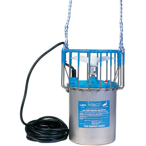
Every December DYC installs 20 deicers to protect the pier from ice damage. The only function of the deicers is pier protection, while this may also protect boats left in the water over winter, DYC is not attempting to protect boats and is not responsible for any damage to boats. The deicers are motors with propellers that move the water around the pier to keep it from freezing. They are stored on shelving in the front of the equipment trailer.
If the water freezes around the pilings, tidal lifting and ice motion will lift or lean pilings resulting in dock damage. Deicers are installed between outer pilings on both sides of the pier to move water towards the shore and remain in the water all winter. Other deicers are placed along the pier to move water under the pier and towards the ramp and remain on the dock until needed. deicers are only powered on when ice starts developing on the creek. Some years deicers may not be used while other years they will be active for two to eight weeks.
Installation
Preparation
- Remove deicers from trailer and sort into following groups:
- 3/4 hp (standard size units)
- Red group – 4 units
- Green group – 4 units
- White Ice Eater brand unit with some black paint.
- 3/4 hp unit with blue paint on bottom.
- 3/4 hp unit with attached dock mount.
- All others.
- 1/2 hp units
- 2 units – both have blue tops
- 3/4 hp (standard size units)
- Take the red and green group to the boat ramp for loading on the boat. Boat crew will install as follows:
- reds – on east side outer pilings.
- greens – on west side outer pilings (one green unit has a short cord, use at slip 16).
- Take the white ice eater unit with black paint to between slips 60/62.
- Take the 3/4 hp unit with blue paint to the first finger pier on east side.
- Take the 3/4 hp unit with attached dock mount about halfway to the gate on the dock.
- Take all other units to dock for placement (use chart below for install).
General Notes
- Built-in cords on all outboard units are same length.
- Deicers use ONLY 30A circuits (no household circuits)(except on shore pole).
- All 30A marine circuits are accessed via Y-connector adaptor (ie. pigtail). Max 2 deicers per box.
- Any boat plugged-in to a 30A box (ie. circular plug) will have to adapt to the Y-connector.
- Note-all outlets are 120VAC.
- Outlets change year to year based on which wintering-over boats are plugged in, try to disturb as few as possible.
Install Notes
- Careful not to put any tension on the cords, but not so loose the prop can get them, try to arrange a fair lead when operating, especially with outboard units.
- 1/2 hp units have a blue top, 3/4 have black top.
- For tie-up, use eyelets where available, otherwise wrap around piling.
Checklist
- Y-connectors are held in a “down” position via nail in piling (to keep water out).
- Extension cord connections: electrical tape the connection to keep it waterproof.
- Note- circuit plug-in vary from year to year in an attempt to unplug as few boats as possible, start hookup at shore end since most boats near shore do not use shore power.
Inboard group
- Installed, tested, then placed on dock until needed.
- The cord points toward the outlet to be used.
- X means outlet is across dock.
- P means outlet is on pole or panel.
| slip | box # | box location | extension cord | size (hp) | comment | |
|---|---|---|---|---|---|---|
| 2 | 6 | slip 8 | long | 3/4 | ensure cord pointing toward slip 8 | |
| 7 | 4 | slip 7 | 1/2 | blue top | ||
| 12 | 6X | slip 9 | 3/4 | |||
| 19 | 13P | slip 27 | long | 3/4 | ||
| 28 | 3 | slip 30 | 3/4 | |||
| 36 | 3 | slip 36 | 3/4 | |||
| 39 | 26 | slip 40 | 1/2 | blue top | ||
| 48 | 7 | slip 46 | 3/4 | |||
| 51 | 9 | slip 51/53 | 3/4 | |||
| 60 | 11 | slip 58 | 3/4 | black paint "Ice Eater", blows west from dock | ||
| 63 | 11X | slip 58 finger | med | 3/4 | blue paint, blows to ramp from finger pier | |
| dock | 3P | shore pole | extra long | 3/4 | pole and flange for 'dockmount' blows to ramp | |
Outboard groups
- Hung from two outer piles, stay in water all winter.
- Hang as low as possible, angle upwards, can “surface” in low tides, wind cords around slip rope.
- Use painted eyes on pilings.
- 2 units below marked T are located on T dock
- Cords must point toward dock for unit to blow toward shore.
| slip | box # | box location | extension cord | hp |
|---|---|---|---|---|
| 1T | 20 | slip 1 | long | 3/4 |
| 13 | 14 | slip 17 | med | 3/4 |
| 29 | 1X | slip 38 | long | 3/4 |
| 45 | 9 | slip 41 | med | 3/4 |
| slip | box # | box location | extension cord | hp |
|---|---|---|---|---|
| 2T | 20 | slip 6 | long | 3/4 |
| 16 | 14 | slip 17 | long, short cord on deicer, join over pile | 3/4 |
| 30 | 1 | slip 31 | med | 3/4 |
| 46 | 7 | slip 46 | 3/4 |
Circuit Boxes
Shore pole is powered via the shore master switch (electrical panel on the shore pole). Switch also powers the shore street light. Dock circuits are marked in panel on dock.
Circuit Breaker Assignments
| Circuit # | Type | Slip |
|---|---|---|
| Grey - Bubbler | Red - 20A circuit | |
| 1 | 30A Marine | 31 |
| 2 | 30A Marine | 1T |
| 3 | 30A Marine | 36 |
| 4 | 30A Marine | 7 |
| 5 | 30A Marine | 41 |
| 6 | 30A Marine | 8 |
| 7 | 30A Marine | 46 |
| 8 | 20A Standard | Spare |
| 9 | 30A Marine | 53 |
| 10 | 30A Marine | 23 |
| 11 | 30A Marine | 58 |
| 12 | 30A Marine | 24 |
| 13 | 30A Marine | 27 |
| 14 | 30A Marine | 17 |
| 15 | 30A Marine | 27 |
| 16 | 30A Marine | 18 |
| 17 | 20A Standard | 1 2 10 13 16 |
| 18 | 30A Marine | 10 |
| 19 | 20A Standard | 17 20 21 24 25 |
| 20 | 30A Marine | 6 |
| 21 | 20A Standard | 43 44 53 54 61 62 |
| 22 | 30A Marine | 5 |
| 23 | 20A Standard | 30 31 34 35 38 39 |
| 24 | 30A Marine | 9 |
| 25 | 30A Marine | 28 |
| 26 | 30A Marine | 40 |
| ? | 30A Marine | shore |
5 "Standard" type boxes are 20A circuits
22 "Marine" type boxes are 30A circuits
Removal
Here is a guide to spring cleanup of the deicers:
- Using the work boat(remember life jackets), remove the 2 groups of 4 in the water.
- Get them to shore and wash, keeping the groups separate.
- For the dock mount unit, just detach from the dock mounted part, do NOT disassemble.
- While doing the above, dry, retrieve the other units from the dock.
- Repaint red/green as needed.
- Check/replace zincs as needed (tools/supplies in trailer).
- Coil up the cords/lines and affix with tiewraps.
- Store the dock units in trailer.
- Put pigtails in crate in Dockhouse locker.
- Coil all cords, secure w/tie wraps, store in cord locker.
- Store dock mount assembly in trailer.
- Cover dock mount dock part with traffic cone secured to dock.